
Tutorial: USB-to-serial cable for img2track
Here we provide instructions for making the cable to connect your computer to your knitting machine. It's not the easiest thing to do, but neither is operating a knitting machine! Or you may order a cable from us.
This is a revised and updated tutorial based on the Adafruit Electro-knit Cable tutorial created by Becky Stern. (The FTDI cable programming is now done with the FT_PROG utility program, which replaced the older utility called MProg. We invert the RTS# signal so it can be used on pin 3. The connector wiring is simplified.)
img2track and similar programs communicate with Brother knitting machines using a data port originally intended for a Brother FB-100 floppy disc drive. This port is available on Brother models 930, 930e, 940, 950i, 965i, and 970.
To connect a computer to the knitting machine, we use a USB-to-serial cable. One end has a USB connector to plug into your computer. The other end has a special connector to plug into the port on the back of the knitting machine. The cable contains a converter chip that translates between USB signals and the TTL signals used by the knitting machine.
We recommend the TTL-232R-5V, made by Future Technology Devices International (FTDI). However, these are not made with a connector to fit the knitting machine. The Brother knitting machines use a nonstandard 2x4 pin data port. Therefore we must modify the cable to attach a matching connector. This modification does not require cutting or soldering. You will need a pin, needle-nosed pliers, electrical tape, and a steady hand.
The knitting machine uses reversed-polarity signals, so the converter chip in the cable must be configured appropriately. FTDI supplies a program for this; it is only available for Microsoft Windows. To use it, you will also need to install driver software on the Windows computer.
Preparing the Cable
The following sections describe the steps to prepare the cable.
- Procure FTDI cable and 2x4 connector
- Install driver software
- Configure the FTDI cable
- Change the connector
Procure FTDI cable and 2x4 connector
Here are links to the parts you'll need, from distributors in several countries. We recommend the FTDI TTL-232R-5V USB‑to‑serial converter cable. We've also used the FTDI TTL‑232R‑3V3 without problems. The 2x4 connector we've been using is the Molex 90142‑0008.
- UK:
- FTDI, who make the cable, have headquarters in Glasgow, Scotland. You can purchase the TTL‑232R‑5V cable from them here.
- RS Components Ltd: TTL-232R-3V3, Molex 90142-0008
- US, Canada:
- Adafruit: TTL-232R-3V3
- DigiKey: TTL-232R-5V, Molex 90142-0008
- Mouser: TTL-232R-5V, Molex 90142-0008
- Worldwide:
- Farnell/element14 supplies many countries:
TTL-232R-3V3, Molex 90142‑0008
(put your country code at the beginning of the URL)
- Farnell/element14 supplies many countries:
Install driver software
The FT_PROG utility you will use in the next step requires that the FTDI driver software is installed on the computer. FT_PROG is available only for Microsoft Windows, so you must use a computer running Windows for this. See Installing driver software on the img2track page.
Configure the FTDI cable
(This must be done on a computer running Microsoft Windows, with the appropriate driver installed in the last step.)
- Download FT_PROG, the FTDI EEPROM Programming Utility, and extract the contents of the zip file.
- FT_PROG requires Microsoft .NET Framework 4.0. If FT_PROG won't run, you may need to install this. See the instructions at the previous link to obtain it.
- Double-click FT_PROG.exe to run the program.
- Check that the cable is plugged into a USB port on the computer.
- In Devices menu, select "Scan & Parse". FT_PROG should scan the cable.
- Double-click "Hardware Specific".
- Click "Invert RS232 Signals".
- On the right, check these three boxes:
- Invert TXD
- Invert RXD
- Invert RTS#
- In Devices menu, select "Program".
- In the dialog window that opens, click the Program button.
- Wait till "Ready" shows in the bottom left corner of the dialog.
- In the File menu, select "Exit" to quit FT_PROG.
Change the connector
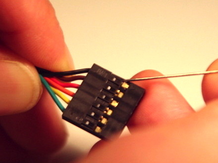
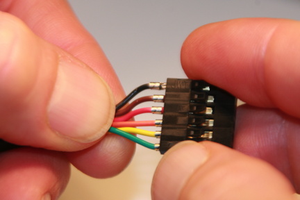
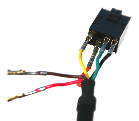
To put the 2x4 pin connector on the USB-to-serial cable, we must first remove the 6 pin connector it comes with. We will reuse the tiny metal sockets attached to each wire in the new 2x4 connector housing.

With a pin, bend back all the plastic tabs on the 1x6 connector.
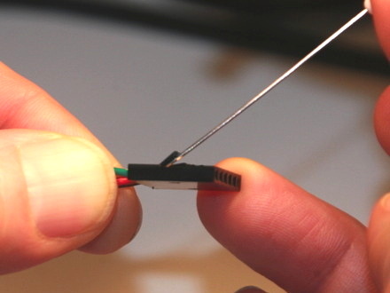
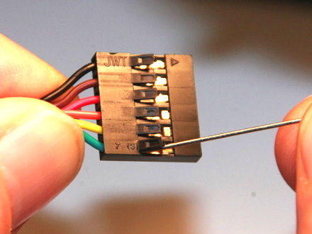
Gently pull on each wire to remove the sockets from the 1x6 connector.
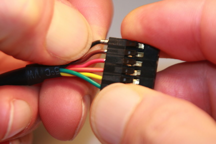
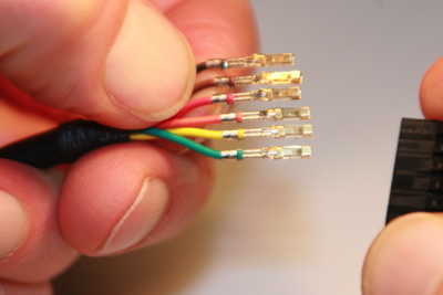
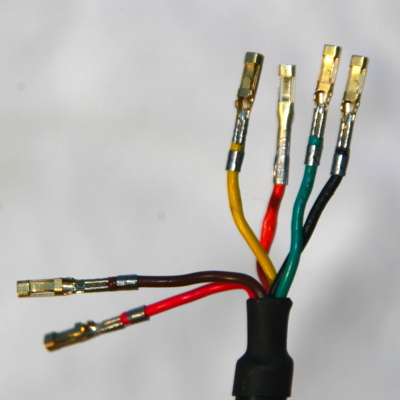
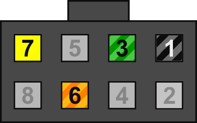
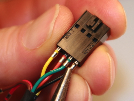
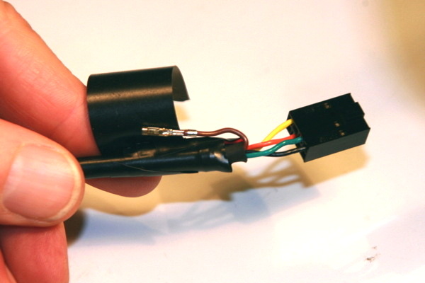
Rearrange the wires in this order: yellow, orange, green, black. Move the other wires to the side. Twist the orange wire 180 degrees so that its socket is facing down. (It is the only one that goes in the bottom row.) Position each socket in the 2x4 connector exactly as shown in the color-coded diagram.
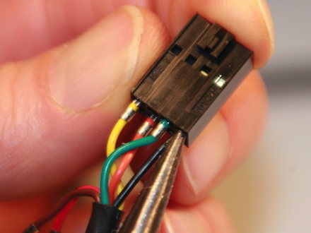
Carefully grab each wire with a needle-nosed plier just below the socket, and push the socket entirely into the 2x4 connector.
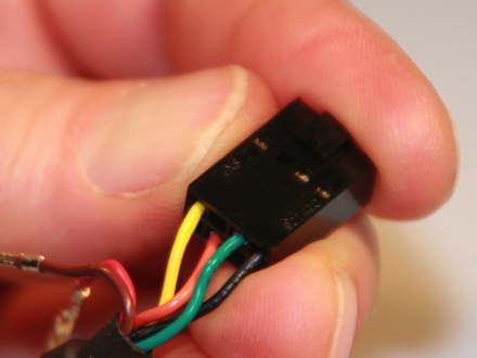
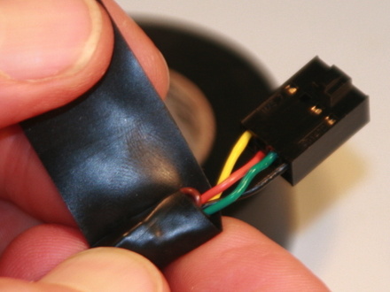
Wrap the unused brown and red wires against the cable with electrical tape. Use two layers of tape between them.
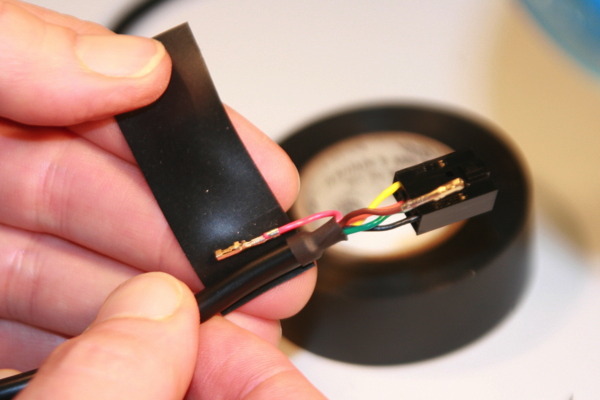
Wrap the end of the cable, the wires, and half of the connector with two or three layers of electrical tape, for durability and strain relief.
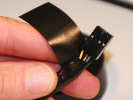
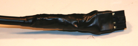
The connector will be plugged into the knitting machine data port with the notch on the top.
(page revised 2023-01-03)